Choose the support conditions and enter the slab and its loads: the tool calculates the deflection, the bending and twisting moments and the reinforcement design moments (Wood-Armer), and maps them over the whole slab.
How to use it
- Each edge is simply supported, clamped or free; the layouts offered (deck slab, slab on three sides, cantilever…) are starting points.
- Loads can be combined: uniform loads, rectangular loads (wheels), point loads, and the EN 1991-2 LM1 tandem and LM2 axle, placed at the centre of the slab and then movable.
- Rectangular loads can be spread at 45° through the surfacing and the concrete down to the mid-plane (EN 1991-2, 4.3.6).
- Choose the quantity shown on the map (deflection, Mx, My, Mxy, Wood-Armer moments for the bottom and top layers); hover over or tap the map to read the values at any point.
Assumptions
- Isotropic Kirchhoff thin plate of constant thickness, linear elasticity and small displacements: thickness below about one tenth of the smallest span.
- Conforming plate finite element analysis (Bogner-Fox-Schmit) on a regular mesh; checked against fourteen handbook cases (Navier series, clamped plates, Pigeaud-type rectangular loads, strips with free edges), with a difference below 1%.
- Moments per metre width: Mx stresses the bars parallel to x, positive when the bottom fibre is in tension; Wood-Armer moments for orthogonal reinforcement along x and y.
- Rigid line supports; no punching shear, shear force or cracking effects. Unfactored loads: combinations and checks according to the Eurocodes remain to be carried out.
Example
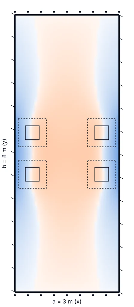
Bridge deck slab, 25 cm thick, 3 × 8 m, fixed on the girders, under its self-weight and the centred LM1 tandem, dispersed down to the mid-plane.
- Support Mx
- −50.3 kN·m/m
- Span Mx
- 13.0 kN·m/m
- Wood-Armer bottom x
- 14.7 kN·m/m
- Deflection
- 0.21 mm
The fixed-end moment under the wheels governs. Characteristic values: to be factored, then checked with the “Simple bending” sheet.
Method, limits and references
Kirchhoff thin plate calculated with Bogner-Fox-Schmit conforming finite elements; wheel loads dispersed at 45° through surfacing and concrete; reinforcement design moments by the Wood-Armer method.
D = E·h³ / (12·(1 − ν²)) = 44,760 kN·m; u = u0 + 2·hr + h = 0.81 m
Limits
- Rectangular, isotropic, constant-thickness thin slab (h ≤ L/10 approx.); rigid line supports.
- Tandem placed by the user: the most unfavourable position is not searched for.
- No shear, punching or cracking.
References: EN 1991-2 (§4.3.2 and §4.3.6); handbook: plates.
Checks: 14 reference cases (Navier, fixed plates, Pigeaud-type loads), maximum difference 0.72%.
Frequently asked questions
Why Wood-Armer moments?
Bars are placed along x and y; the Wood-Armer method adds the effect of the twisting moment Mxy to the moment to be carried: 14.7 kN·m/m instead of 13.0 in the example.
How do I place the tandem in the worst position?
By moving it: close to a fixed edge for the fixed-end moment, at the centre for the span moment. The tool recalculates at each move.
What is the dispersal of wheel loads for?
The load spreads at 45° down to the mid-plane (EN 1991-2, 4.3.6); without dispersal, moments under the wheel are overestimated.
See also
Preliminary design aids, provided for guidance only: they do not replace calculations prepared by an engineer. Found an error, have a suggestion? Write to us.